Harmonic Drive Actuator (MITE)
Thesis
Since late 2025, I have been working nights and weekends on a bipedal humanoid. No arms or head, just the legs and torso (to house the electronics, batteries, etc). For the muscles of the humanoid, I choose to go with harmonic drives.
Now why are harmonics so popular in humanoids and industrial robot arms?
- Extremely precise, near zero backlash - Due to high % of teeth engaged at any one time
- High reduction ratios in small diameters - can easily hit 100:1 in <100mm diameter
- Lightweight components - the flex spline is a thin walled circle
So what are the drawbacks of these drives?
- Very expensive - can be 5X the cost of a simple planetary BLDC acuator.
- Very calculation intensive (more on this below)
Calculation Hurdles
While reading current papers on harmonic drive design, I realized there were no good calculators. All of the fatigue life calculations, along with the conjugate teeth design was most likely propeitery software at the top robotics companies.
So I built my own:
Cross Section
Side View
Top View
Simulation
One of the main hurdles in harmonic drive design is simulation validation. It is complex and timely, as each calcualator generated tooth geometry needs to be validated / tweaked using FEA.
For my simulation process I started with the flexspline cup and the wave generator (solidbody). I then ran a non linear deformation study to obtain the deformed flex spline shape. From there, I could export that deformed shape and apply a constant torque to it, to rotate it along the circular spline and get our meshing stresses.
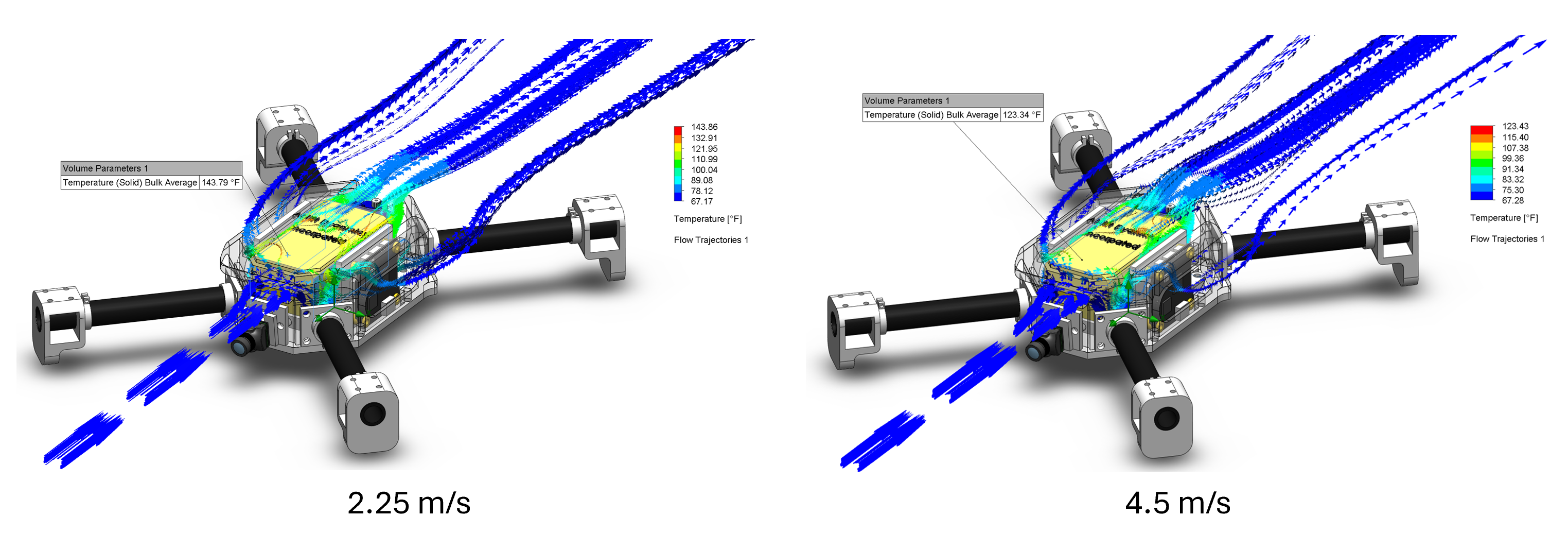
Battery Cooling
To ensure the landing legs could take a hard landing impact, FEA was run. Through some rough calculations, the force of a 15mph deceleration was found and applied evenly to all four feet. Given that plastics are hard to simulate, our factor of safety was lower than imagined at a 2. This is likely due to the complexity of printed plastics anistropic nature.
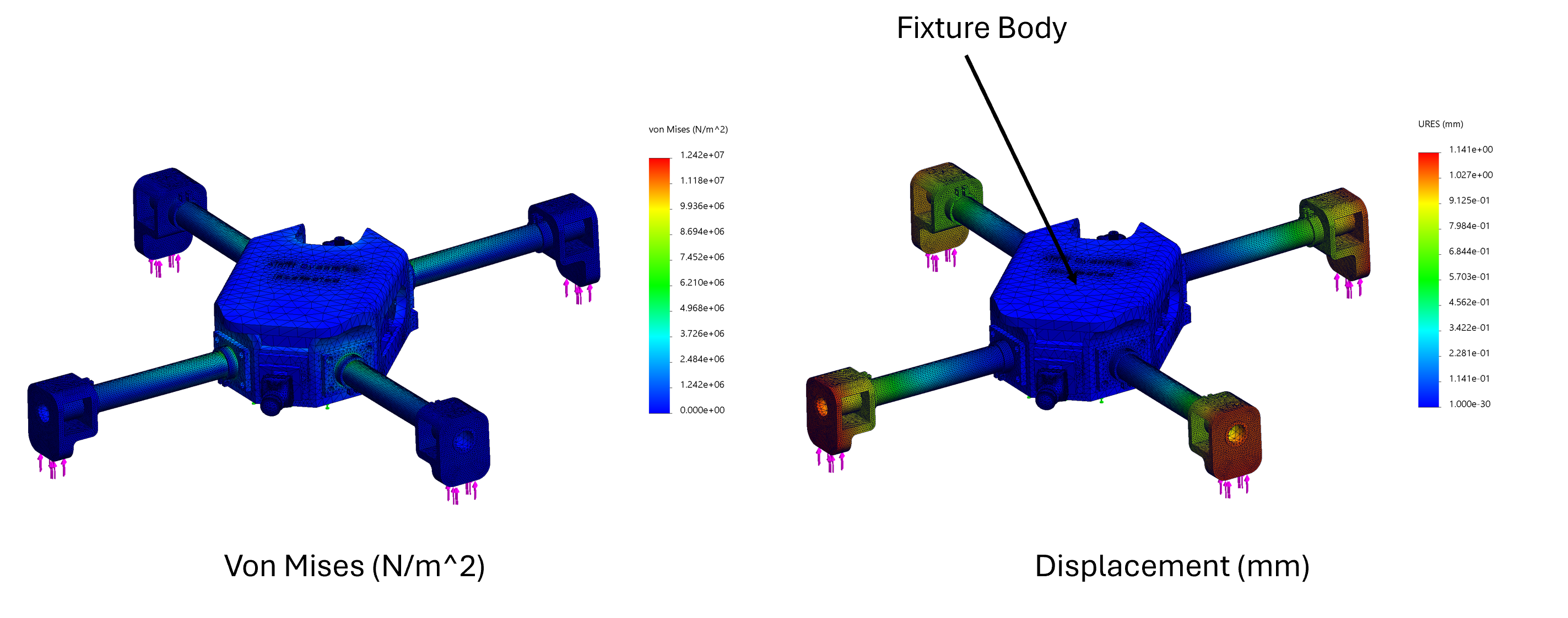
15mph Landing